
Using four full adders under Custom in the left panel two 4-bit inputs with four switches and five light bulbs 4 bits output plus a carry out assemble your 4-bit adder Drag out and name labels for the inputs and output. Priority encoder circuit with truth table for 8-bit and 4-bit are explained in the below section.

Vhdl Code For Full Adder Coding Computer Science Neon Signs
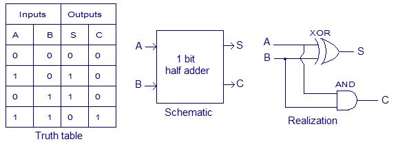
These are generally denoted by S and C-OUT.

. Assumed that an XOR-gate takes 3 delays to complete the delay imposed by the critical path of a full adder is equal to The carry-block subcomponent consists of 2 gates and therefore has a delay of Full Adder 4 bit. If you need it very much you have to generate it. Draw the truth table-.
Half Adder Truth Table. There are eight possible combinations of the three inputs of a full adder. Truth Table for a Full Adder.
The connection of full-adders to create binary adder circuit is discussed in block diagram below. Rekisteröityminen ja tarjoaminen on ilmaista. These are the least possible single-bit combinations.
You are unlikely to find full truth table of a 4-bit adder circuit. Circuit for 3 input OR gate. But I must warn you it is going to be large because there are so many combinations of input a 4-bit adder can have.
If a 4-bit sum is equal to or less than 9 it is a valid BCD number. 4 bit Full Adder Construct a 4 bit full adder as presented in Figure 1. Full Adder Truth Table - 17 images - lec20 half adder full adder truth table logic circuit combinational circuit adder circuits notesformsc full subtractor.
The 2-bit half adder truth table is as below. Each carry-out should go to the carry-in of the next adder. 2 Bit Full Adder - 17 images - gallery 2bit binary adder pdf layout design of a 2 bit binary parallel ripple carry adder using drc results shows no errors 3 bit adder multisim live.
Design of Full Adder using Half Adder circuit is also shown. Identify the input and output variables-Input variables A B C in either 0 or 1 Output variables S C out where S Sum and C out Carry. For generating truth table you have to put all the inputs and then find out the output bits.
Thus the equations can be written as. The hints for construction are given in the note below. B4 A4 B3 A3 B2 42 81 AL MO C3 C1 Full Adder Full Adder C4 Full Adder Full Adder - 1 - - 1 S3 S1 Figure 14 Bit.
If a 4-bit sum is greater than 9 or if a carry out of the 4-bit group is generated it is an invalid result. With the above full adder truth-table the implementation of a. Advantages of Carry Look Ahead Adders.
A combinational circuit can hold an n number of inputs and m number of outputs. Etsi töitä jotka liittyvät hakusanaan Four bit adder truth table tai palkkaa maailman suurimmalta makkinapaikalta jossa on yli 21 miljoonaa työtä. 00 0 01 1 10 1 11 10.
The two outputs of the full adder are known as sum and carry-out. The four fundamental addition operations for multiple binary numbers which are single bit are as follows. These are typically referred to as A B and C-IN respectively.
In report you should post a screenshot of your circuit and truth table. But I must warn you it is going to be large because there are so many combinations of input a 4-bit adder can have. A sub-circuit for 3 input OR gate has been made and used in the main circuit.
The inputs of the full adder are given as input 1 input 2 and carry-in. 2s complement of binary number Sub-Circuit. Equipment 1- Electronic WorkBench Truth Table Bit Full Adder-4 C3 C2 C1 C0 S3 S2 S1 S0 B3 B2 B1 B0 A3 A2 A1 A0 0 0 0 0 0 0 0 0 0 0 0 0 0 0 0 0 1 0 0 0 0 0 0 0 1 0 0 0 1.
Answer 1 of 3. In this implementation carry of each full-adder is connected to previous carry. 4 Bit Binary Adder Truth Table - 17 images - digital logic design 2 design a 4 bit grey to binary code converter full adder truth table and logic diagram decoration full adder truth table 4 bit decoration items image.
Add the two BCD numbers using the rules for binary addition. The 4-bit priority encoder contains 4 inputs and 2 outputs along with one valid output. Full adder contains 3 inputs and 2 outputs sum and carry as shown- Full Adder Designing- Full adder is designed in the following steps- Step-01.
Through this article on Adders learn about the full adder half adder Binary Parallel Adders Carry Look Ahead Adder BCD Adder Serial Adder with circuit diagrams and truth tables. But the result for 11 is 10 the sum result must be re-written as a 2-bit output. 2 Bit Multiplier 2 Bits Bits Circuit.
You are unlikely to find full truth table of a 4-bit adder circuit. Take into account the process of trying to add multiple binary numbers that is the basic operations executed by a computer system. Karnaugh Map to Circuit.
Use a Low Constant for the original carry-in. Lets start with the expressions for the FULL ADDER -Sum_out in_x XOR in_y XOR carry_in Carry_out in_x AND in_y OR in_x XOR in_y AND carry_in Next we will draw the circuit of 4 Bit Binary Adder. Simply a circuit in which different types of logic gates are combined.
If you need it very much you have to generate it.

Full Adder Schenatic Electronics Electrical Electronics Circuit Electricity Electrical Components

Binary Multiplier Types Binary Multiplication Calculator Binary Electronic Schematics What Is Digital
Difference Between Half Adder And Full Adder Coding Informative Truth

Carry Select Adder Vhdl Code Coding The Selection Carry On

Binary To Gray Code Converter 4 Bit Coding Binary Converter

3 Bit Multiplier Logic Design Circuit Digital

Half Adder And Full Adder Circuits Using Nand Gates Circuit Circuit Diagram Microsoft

Vhdl Code For Full Adder Coding Computer Science Binary Number

Moore State Machine Vhdl Code Coding States Detector

Binary Multiplier Types Binary Multiplication Calculator Electronic Circuit Projects Electronic Schematics Circuit Projects

Carry Look Ahead Adder Vhdl Code Coding Carry On Tutorial

4 Bit Ripple Carry Adder Vhdl Code Coding Ripple Carry On

Verilog Code For Pipelined Mips Processor Processor Coding The Unit

Design 4 Bit Voting Combinational Eircuit That Has Two Outputs One Output To Indicate Mejority And Snother To Indicate A Tie Vot Homework Help Equations Logic

Verilog Code For Button Debouncing Coding Buttons Electronics Projects

Experiment Write Vhdl Code For Realize All Logic Gates Logic Experiments Coding

Pin On Vhdl Tutorials
Binary Adder Subtractor Construction Types Applications Electronic Engineering Electronic Schematics Engineering Technology

One Way We Could Expand The Capabilities Of Either Of These Two Counter Circuits Is To Regard The Q Outputs As Another Set Of Four B Counter Expand Binary


